
Introduction
In the world of electronics and engineering, the ability to read and interpret schematics is a fundamental skill. But what exactly are schematics, and why are they so important?
Schematics, or circuit diagrams, are visual representations of electronic circuits. They use symbols to represent different electronic components and show how these components are interconnected.
We’ll start with the basics, explaining what schematics are and why they’re important. Then, we’ll delve into the various symbols used in schematics and what they represent. But we won’t stop at just recognizing symbols.
This guide will also teach you how to interpret the connections between components, understand designators and values, and even avoid common mistakes that people make when reading schematics.
By the end of this guide, you’ll have a solid foundation in reading schematics, equipping you with the knowledge you need to tackle electronic circuit design with confidence. So, are you ready to get started on this exciting journey into the world of schematics?
The Basics of Schematics
What is a Schematic?
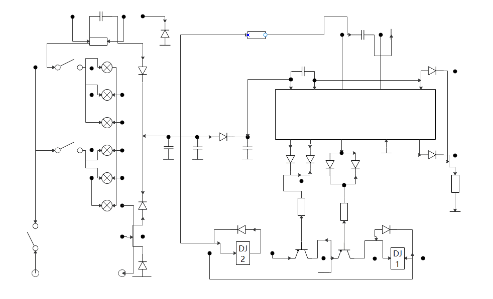
A schematic, also known as a circuit diagram, is a visual representation of an electronic circuit. It uses standardized symbols to represent electronic components and shows how these components are connected to form a circuit. Unlike a pictorial diagram, a schematic doesn’t aim to represent the physical layout of the components. Instead, it focuses on the electrical connections between components, providing a clear picture of how the circuit functions.
Why are Schematics Important?
You might be wondering, why are schematics so important? Well, schematics are the language of electronics. They are essential tools for anyone involved in designing, building, or troubleshooting electronic circuits. It from a conceptual design into a physical electronic device.
Schematics are also crucial for communication. They allow engineers and technicians around the world to share circuit designs, discuss problems, and find solutions. Whether you’re working on a small DIY project or a large-scale industrial system, being able to read and understanding schematics is a vital skill.
In the next section, we’ll start diving into the various symbols used in schematics and what they represent. This will be your first step towards becoming fluent in the language of electronics.
Schematic Symbols and Their Meanings
Basic Symbols
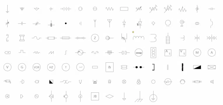
In the world of schematics, symbols are the alphabet. They represent the various components that make up an electronic circuit. Let’s start with some of the most basic symbols you’ll encounter.
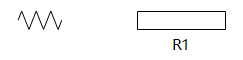
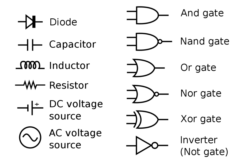
Resistors: A resistor is represented by a zigzag line. Resistors are used to limit the flow of current in a circuit. They’re fundamental components in electronics and come in many different values, measured in ohms. For example, you might see resistors in a circuit designed to control the brightness of an LED. The higher the resistance, the dimmer the LED will be.
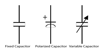
Capacitors: Capacitors are represented by two parallel lines. Capacitors store electrical energy and can release it when needed. Capacitors are crucial in many electronic devices, helping to regulate power supply and filter noise. For instance, in a radio, capacitors are used in the tuner to select the desired station.
Inductors: Inductors are represented by a series of curved lines or loops. Inductors store energy in a magnetic field when electrical current passes through them. Inductors are used in a variety of applications, including power supplies and radio frequency circuits. In a power supply, an inductor might be used to smooth out the output voltage.

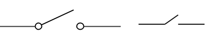
Switches: A switch is represented by a break in a line with a short, angled line connecting to the break. Switches allow for control of the electrical current in a circuit, enabling it to be turned on or off. You encounter switches in your daily life, from the light switch on your wall to the power button on your computer.
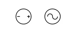
Power Sources: Power sources, such as batteries or power supplies, are represented by a series of alternating long and short parallel lines. They provide the electrical energy needed for the circuit to function. Without a power source, your electronic devices, from your smartphone to your refrigerator, wouldn’t be able to operate.
Intermediate Symbols
As we delve deeper into the world of schematics, we encounter more complex components. Let’s explore some of these intermediate symbols.
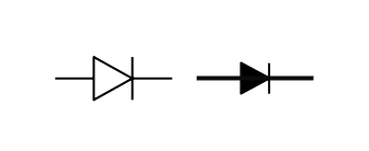
Diodes: A diode is represented by a triangle pointing towards a line. Diodes allow current to flow in one direction but not the other. They’re often used for converting alternating current (AC) to direct current (DC), a process known as rectification. Light-emitting diodes (LEDs) are a type of diode that emits light when current flows through them.
Transistors: Transistors are represented by a combination of diode symbols. Transistors are crucial components in electronics as they can amplify signals or act as switches. They’re the building blocks of modern digital circuits and can be found in almost every electronic device, from your smartphone to your car’s engine control unit.
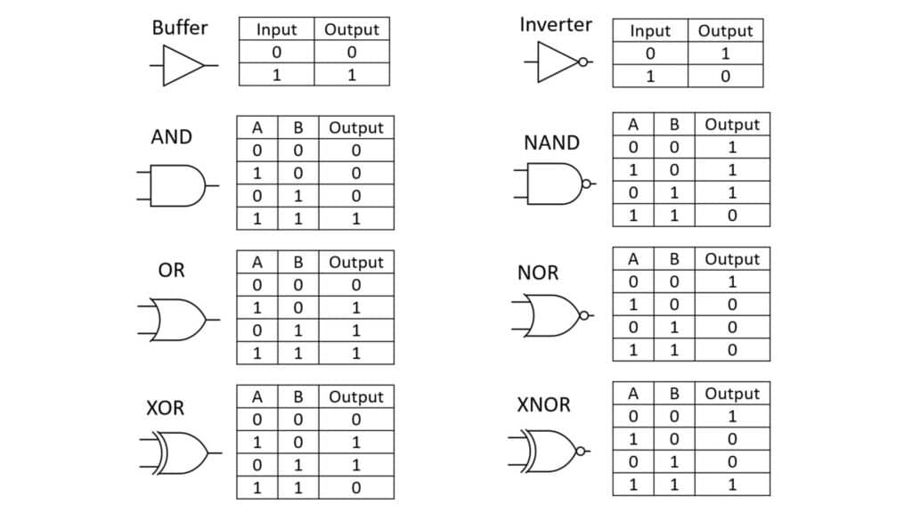
Digital Logic Gates: Logic gates are the fundamental building blocks of digital circuits. They perform basic logical functions that are fundamental to digital circuits. The most common logic gates are AND, OR, and NOT gates. Each has a unique symbol.You can learn more about Digital Logic Gates here.
Advanced Symbols
As we continue our journey into the world of schematics, we encounter even more complex symbols. These represent advanced components that are used in more complex circuits. Let’s explore some of these advanced symbols.
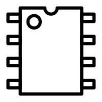
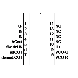
Integrated Circuits (ICs): Integrated circuits, or ICs, are represented by a rectangular box with multiple lines extending from it. Integrated circuits are essentially miniaturized circuits that have been etched onto a small chip of semiconductor material. They can perform a wide range of functions, from simple logic operations to complex microprocessor tasks. ICs are the heart of modern electronics, found in everything from computers to cars to mobile phones.
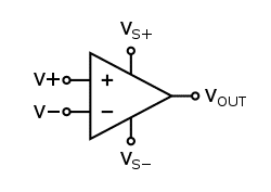
Operational Amplifiers (Op-Amps): Operational amplifiers, or op-amps, are represented by a triangular symbol with five terminals: two inputs, two power connections, and one output. Op-amps are versatile devices that can be used to amplify signals, filter noise, perform mathematical operations, and more. They’re a key component in many analog electronic circuits.
Connectors: Connectors are represented by a variety of symbols, depending on their type. Connectors provide a means for attaching wires, cables, or printed circuit boards together to form a complete circuit. They’re essential for building and maintaining electronic devices.

Other Schematic Symbols

While we’ve covered some of the most common schematic symbols, it’s important to note that there are many more symbols out there. These represent a wide range of electronic components, from simple elements like fuses and relays to more complex devices like transformers and microcontrollers.
If you’re interested in learning more about these other symbols, there are many resources available. Websites like Electronics Tutorials offer comprehensive guides to schematic symbols. There are also many books and online courses that can provide a more in-depth understanding of electronics and schematics.
Remember, learning to read schematics is a journey. Don’t be discouraged if you don’t understand everything right away. With time and practice, you’ll become more comfortable with schematics and be able to interpret even the most complex circuits.
Now that we’ve covered the basics of schematic symbols, let’s move on to another important aspect of reading schematics: understanding designators and values.
How to Read Schematic Designators and Values
Once you’ve become familiar with the symbols used in schematics, the next step is to understand how to read designators and values. These are crucial for understanding the specifics of a circuit and how it operates.
Designators: Each component in a schematic is typically labeled with a designator. Designators are usually a letter followed by a number. The letter indicates the type of component, while the number helps differentiate between multiple components of the same type. For example, resistors are often labeled with an “R” (R1, R2, R3, etc.), capacitors with a “C” (C1, C2, C3, etc.), and so on.
Values: Next to each component symbol, you’ll often see a value. This value tells you the specific characteristics of the component. For instance, a resistor might be labeled “R1 220Ω”. This tells you that resistor R1 has a resistance of 220 ohms. Similarly, a capacitor might be labeled “C1 10μF”, indicating that capacitor C1 has a capacitance of 10 microfarads.
Understanding designators and values is key to interpreting a schematic and building or troubleshooting a circuit. It allows you to identify each component and understand its role within the circuit.
Table of Common Components and Their Name Prefixes
In schematics, each component is typically labeled with a designator that starts with a specific letter. This letter is often referred to as a name prefix. Here’s a table of some common components and their typical name prefixes:
| Component | Name Prefix | Description |
|---|---|---|
| Resistor | R | Limits the flow of electric current. |
| Capacitor | C | Stores and releases electrical energy. |
| Inductor | L | Stores energy in a magnetic field. |
| Diode | D | Allows current to flow in one direction only. |
| Transistor | Q | Amplifies or switches electronic signals and electrical power. |
| Integrated Circuit | U | A set of electronic circuits on one small flat piece (or “chip”) of semiconductor material. |
| Connector | J / P | Connects electrical or optical signals between two devices. |
| Switch | S | Opens or closes an electrical circuit. |
| Fuse | F | Protects an electrical circuit from damage caused by excess current. |
| Crystal | Y | Provides a clock signal to an electronic circuit. |
| Test Point | TP | Provides access to a point in an electronic circuit. |
Practical Guide to Reading Schematics
Reading a schematic is a fundamental skill in electronics. It allows you to understand how a circuit works, troubleshoot problems, and design your own circuits. In this guide, we’ll cover some key aspects of reading schematics, including understanding connections, identifying blocks and voltage nodes, and referencing component datasheets.
Understanding Connections
In a schematic, the lines represent electrical connections between components. These connections are often referred to as “nets”. A point where two or more nets meet is called a “node”. When three or more lines meet, it’s called a “junction”.
Nets are often labeled with names to make it easier to understand their function. For example, a net connected to the positive terminal of a power supply might be labeled “VCC” or “VDD”, while a net connected to the negative terminal might be labeled “GND” (short for “ground”).
Understanding the connections between components is crucial for understanding how the circuit works. It allows you to trace the path of current through the circuit and see how the components interact with each other.
Identifying Blocks and Voltage Nodes
Many circuits can be broken down into smaller, simpler “blocks”. Each block performs a specific function and is often made up of several components. For example, a power supply circuit might have a rectifier block, a filter block, and a regulator block.
Identifying these blocks can make a complex schematic much easier to understand. It allows you to focus on one part of the circuit at a time and understand its function.
Similarly, identifying “voltage nodes” can also be helpful. A voltage node is a point in the circuit where the voltage is known, either because it’s connected to a power supply or because it’s connected to ground. Knowing the voltage at different points in the circuit can help you understand how the circuit works.
Referencing Component Datasheets
Finally, it’s important to know how to reference component datasheets. A datasheet is a document that provides detailed information about a specific component, including its electrical characteristics, pin configuration, and recommended operating conditions.
Datasheets are crucial for understanding how a component works and how to use it in a circuit. They can provide valuable information that’s not shown in the schematic, such as the component’s maximum voltage or current rating, its power dissipation, or the function of each pin.
When reading a schematic, it’s a good idea to have the datasheets for the components on hand. This will allow you to look up any information you need and ensure that you’re using the components correctly.
Common Mistakes and How to Avoid Them
When reading schematics, it’s easy to make mistakes, especially if you’re new to electronics. Here are some common mistakes and tips on how to avoid them:
Mistake 1: Misinterpreting Symbols: One common mistake is misinterpreting the symbols used in the schematic. For example, confusing a capacitor symbol with that of a resistor.
How to Avoid: Familiarize yourself with the most common schematic symbols. Keep a reference guide handy until you’re comfortable with the symbols.
Mistake 2: Misreading Connections: Another common mistake is misreading the connections between components. For example, assuming that two crossing lines are connected when they’re not.
How to Avoid: Remember that in most schematics, a dot is used to indicate a connection. If there’s no dot, the lines are not connected.
Mistake 3: Overlooking Power and Ground Connections: Many beginners overlook the power and ground connections, which are crucial for understanding how the circuit works.
How to Avoid: Always check for power (often labeled as VCC, VDD, or +) and ground (often labeled as GND, VSS, or -) connections in the schematic.
Mistake 4: Ignoring Component Values and Designators: Component values (like resistance, capacitance, etc.) and designators (like R1, C1, etc.) provide important information about the circuit. Ignoring them can lead to misunderstanding the circuit.
How to Avoid: Pay attention to the component values and designators. They can help you understand the function of each component in the circuit.
Mistake 5: Not Referencing Datasheets: Datasheets provide detailed information about components, including their electrical characteristics and pin configurations. Not referencing them can lead to mistakes when interpreting the schematic.
How to Avoid: Always reference the datasheets for the components in the schematic. They can provide valuable information that’s not shown in the schematic.
Remember, everyone makes mistakes when they’re learning something new. Don’t be discouraged if you make mistakes when reading schematics. With practice, you’ll become more proficient and make fewer mistakes.
Advanced Topics in Schematics
Once you’ve mastered the basics of reading schematics, there are some advanced topics that can help you understand more complex circuits. Here are a few:
1. Digital and Analog Circuits: Schematics can represent both digital and analog circuits. Digital circuits use components like logic gates and microcontrollers, while analog circuits use components like resistors, capacitors, and op-amps. Understanding the difference between these two types of circuits can help you interpret more complex schematics. For more information, check out this overview of digital and analog circuits.
2. Circuit Simulation: Many electronics design software tools offer circuit simulation features. These allow you to simulate the behavior of a circuit without having to build it physically. This can be a powerful tool for understanding how a circuit works and troubleshooting potential problems. Try out this online circuit simulator to get a feel for how different components interact in a circuit.
3. PCB Layout: Once a circuit has been designed and simulated, the next step is to create a printed circuit board (PCB) layout. This is a representation of how the components and connections will be arranged on the physical PCB. Understanding PCB layouts can help you move from reading schematics to building actual electronic devices. Here’s a tutorial on how to design a PCB layout.
4. Advanced Components: As you delve deeper into electronics, you’ll encounter more advanced components like microcontrollers, digital signal processors (DSPs), and field-programmable gate arrays (FPGAs). Learning about these components can open up new possibilities for understanding and designing complex electronic systems. This link provides information on advanced components and materials used in electronics.
Remember, learning to read schematics is a journey. Don’t be discouraged if you don’t understand everything right away. Keep practicing, keep learning, and don’t be afraid to ask questions. With time and dedication, you’ll become proficient at reading schematics and understanding electronic circuits.
Conclusion
Learning to read schematics is a fundamental skill in electronics. It allows you to understand how a circuit works, troubleshoot problems, and even design your own circuits. While it can seem daunting at first, with practice, you’ll find that it becomes second nature.
Remember, a schematic is more than just a collection of symbols and lines. It’s a representation of an electronic circuit, a map that shows how different components are connected and interact with each other. By learning to read this map, you can unlock a world of possibilities in electronics.
Whether you’re a hobbyist looking to build your own gadgets, a student studying electronics, or a professional engineer, understanding schematics is a valuable skill that will serve you well in your electronics journey.
FAQs
1. What is a schematic?
A schematic is a diagram that represents an electronic circuit. It uses symbols to represent components and lines to represent connections between components.
2. How do I read a schematic?
Reading a schematic involves identifying the components (using the symbols), understanding the connections between them (represented by lines), and understanding the function of each component in the circuit.
3. What are some common symbols used in schematics?
Some common symbols include a zigzag line for resistors, two parallel lines for capacitors, a triangle for diodes, and circles for transistors and integrated circuits.
4. What are designators and values in a schematic?
Designators are labels used to identify each component in a schematic. They usually consist of a letter (which indicates the type of component) followed by a number. Values indicate the specific characteristics of a component, such as the resistance of a resistor or the capacitance of a capacitor.
5. What are some common mistakes when reading schematics and how can I avoid them?
Common mistakes include misinterpreting symbols, misreading connections, overlooking power and ground connections, ignoring component values and designators, and not referencing datasheets. You can avoid these mistakes by familiarizing yourself with schematic symbols, paying attention to connections and component details, and always referencing datasheets for components.