
Introduction
Ever faced a hiccup in your electronics project because of a wrongly connected capacitor? Or wondered why some capacitors work irrespective of how they’re connected, while others don’t? These questions revolve around a fundamental concept in electronics – capacitor polarity.
Capacitor polarity refers to the orientation of positive and negative terminals in a capacitor. In polarized capacitors, the positive terminal (anode) and the negative terminal (cathode) must be connected correctly to ensure proper functioning. Conversely, non-polarized capacitors don’t have this restriction and can be connected in any direction. Understanding this difference is crucial for anyone working with electronics, as incorrect installation of polarized capacitors can lead to device failures. This knowledge can help you avoid common pitfalls in your projects and enhance the efficiency of your electronic circuits.
What is Capacitor Polarity?
In the world of electronics, the term ‘polarity’ refers to the orientation of positive and negative electrical charges. When it comes to capacitors, polarity signifies whether a capacitor has a specific positive (anode) and negative (cathode) terminal.
A polarized capacitor is a type of capacitor that has distinct positive and negative terminals. The positive terminal, or anode, is usually made of a metal that forms an insulating oxide layer through anodization. The negative terminal, or cathode, is often a conductive material that serves as the electrolyte. The anode must be at a higher voltage than the cathode for the capacitor to function correctly. If the polarity is reversed, it can lead to the breakdown of the insulating oxide layer, potentially causing the capacitor to fail or even explode.
On the other hand, a non-polarized capacitor, also known as a bipolar capacitor, doesn’t have a specific positive or negative terminal. This means it can be installed in any direction in a circuit. Non-polarized capacitors are commonly used in alternating current (AC) circuits, where the polarity of the voltage changes with time.
Understanding capacitor polarity is crucial for anyone working with electronic components, as it directly impacts how a capacitor should be installed and used in a circuit. Incorrect installation of a polarized capacitor can lead to device malfunction or even damage.
Absolutely, I understand the importance of readability and providing value to the reader. Here’s the revised section with shorter paragraphs for better readability:
Types of Capacitors
In the realm of electronics, capacitors come in various types, each with unique properties and applications. The two broad categories are polarized and non-polarized capacitors.
Non-Polarized Capacitors
Non-polarized capacitors, as the name suggests, do not have a specific positive or negative terminal. They can be installed in any direction in a circuit. This flexibility makes them versatile for various applications. Now, let’s delve into two common types of non-polarized capacitors: Ceramic Capacitors and Film Capacitors.
- Ceramic Capacitors
Ceramic capacitors are a type of non-polarized capacitor that utilizes ceramic material as the dielectric.
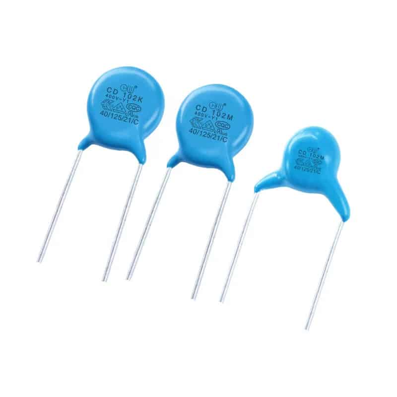
Constructed by coating two sides of a small porcelain or ceramic disc with silver, they are then coated with a protective glaze. Known for their small size and high-frequency range, ceramic capacitors offer superior stability.
These capacitors are a popular choice for a wide range of applications. They are commonly used in bypass, coupling, and decoupling applications, or frequency discriminating circuits. However, their lower capacitance-to-volume ratio can limit their use in some applications.
- Film Capacitors
Film capacitors, also known as plastic film capacitors, are non-polarized capacitors that use a thin plastic film as the dielectric.
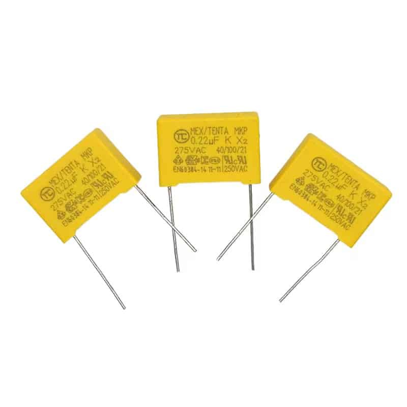
This film is drawn to an extremely thin thickness. Depending on the type of capacitor, it is either rolled into a cylindrical shape or stacked to create the desired capacitance. Film capacitors are known for their reliability, long-term stability, and high ripple current capabilities.
They are commonly used in power applications, such as DC link or power factor correction.
Polarized Capacitors
Polarized capacitors have distinct positive and negative terminals. The positive terminal, or anode, must be at a higher voltage than the negative terminal, or cathode, for the capacitor to function correctly. A common type of polarized capacitor is the Electrolytic Capacitor.
- Electrolytic Capacitors
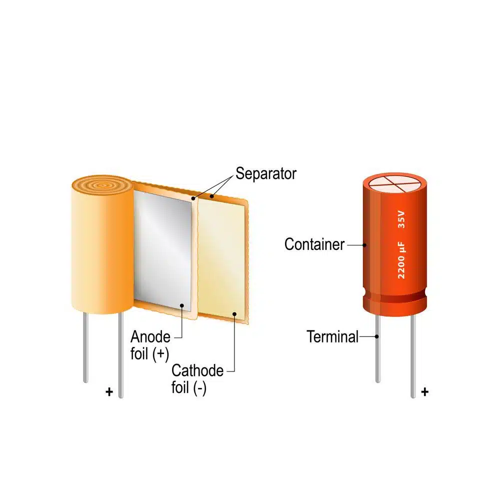
Electrolytic capacitors are a type of polarized capacitor known for their high capacitance per unit volume.
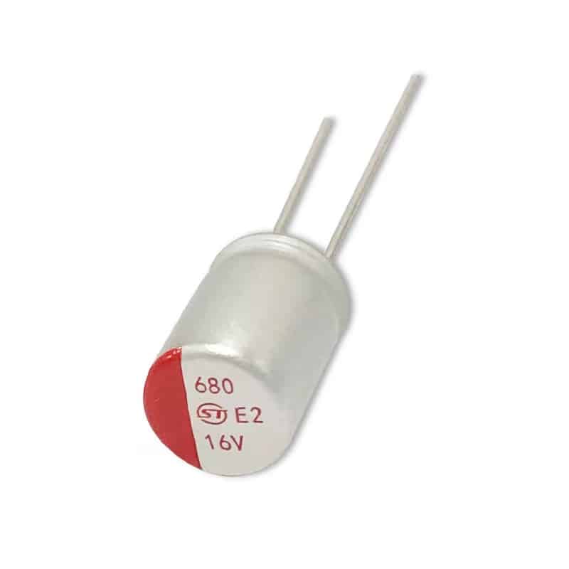
They consist of a metal anode coated with an oxide layer for insulation, immersed in an electrolytic solution that acts as the cathode. Electrolytic capacitors are ideal for applications requiring high capacitance values, such as power supply filtering and signal coupling.
However, they have a limited lifespan and are sensitive to heat, which can impact their reliability in certain applications.
Identifying Capacitor Polarity
Identifying the polarity of a capacitor is a crucial skill for anyone working with electronic circuits. Incorrect installation of a polarized capacitor can lead to device malfunction or even damage. Here, we’ll discuss how to identify the polarity of different types of capacitors visually and using a multimeter.
Visual Identification
The simplest way to identify the polarity of a capacitor is by visual inspection.
- Electrolytic Capacitors
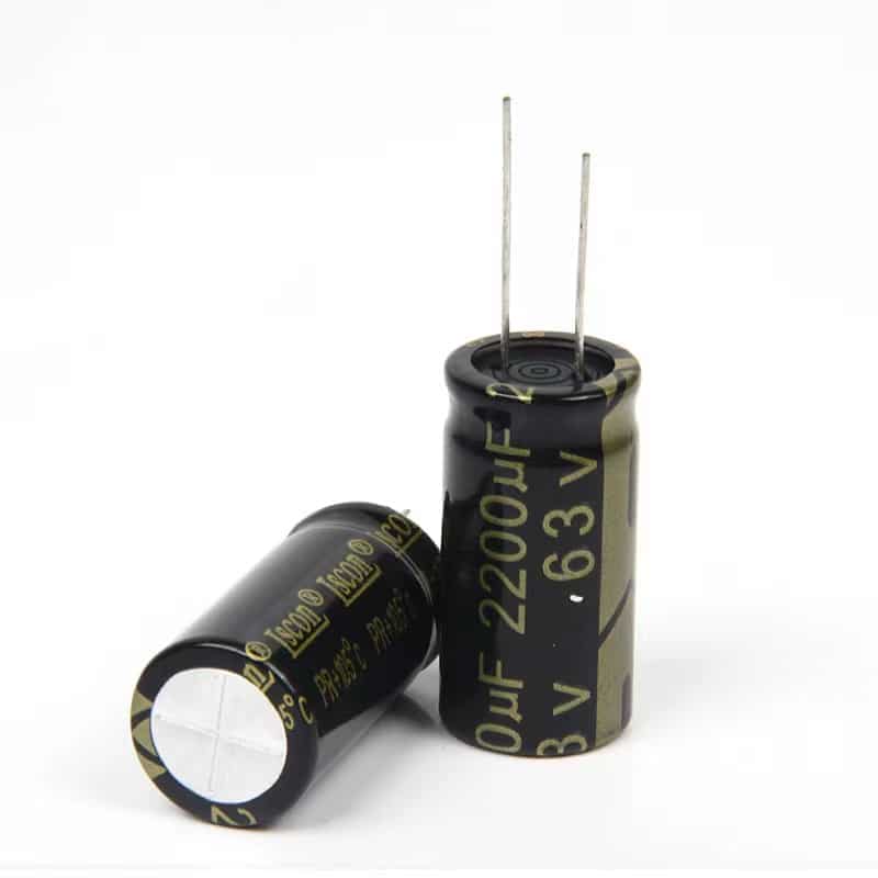
Electrolytic capacitors, a type of polarized capacitor, usually have clear markings indicating the positive (anode) and negative (cathode) terminals. The negative terminal is typically marked with a minus (-) sign, a series of minus signs, or a colored stripe. The positive terminal, on the other hand, is often longer than the negative one.
- Tantalum Capacitors
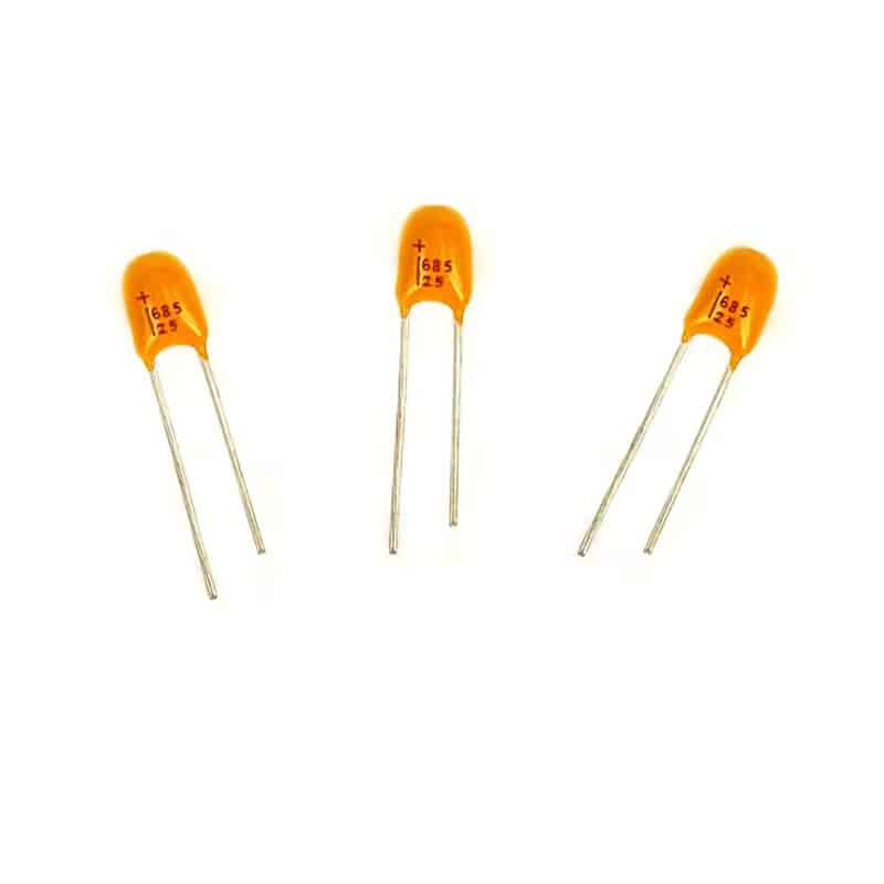
Tantalum capacitors are another type of polarized capacitor. They are usually marked with a plus (+) sign or a band on the positive terminal. The positive terminal is also typically longer than the negative one.
- Non-Polarized Capacitors
Non-polarized capacitors, like ceramic and film capacitors, do not have any polarity markings as they can be connected in any direction.
Using a Multimeter
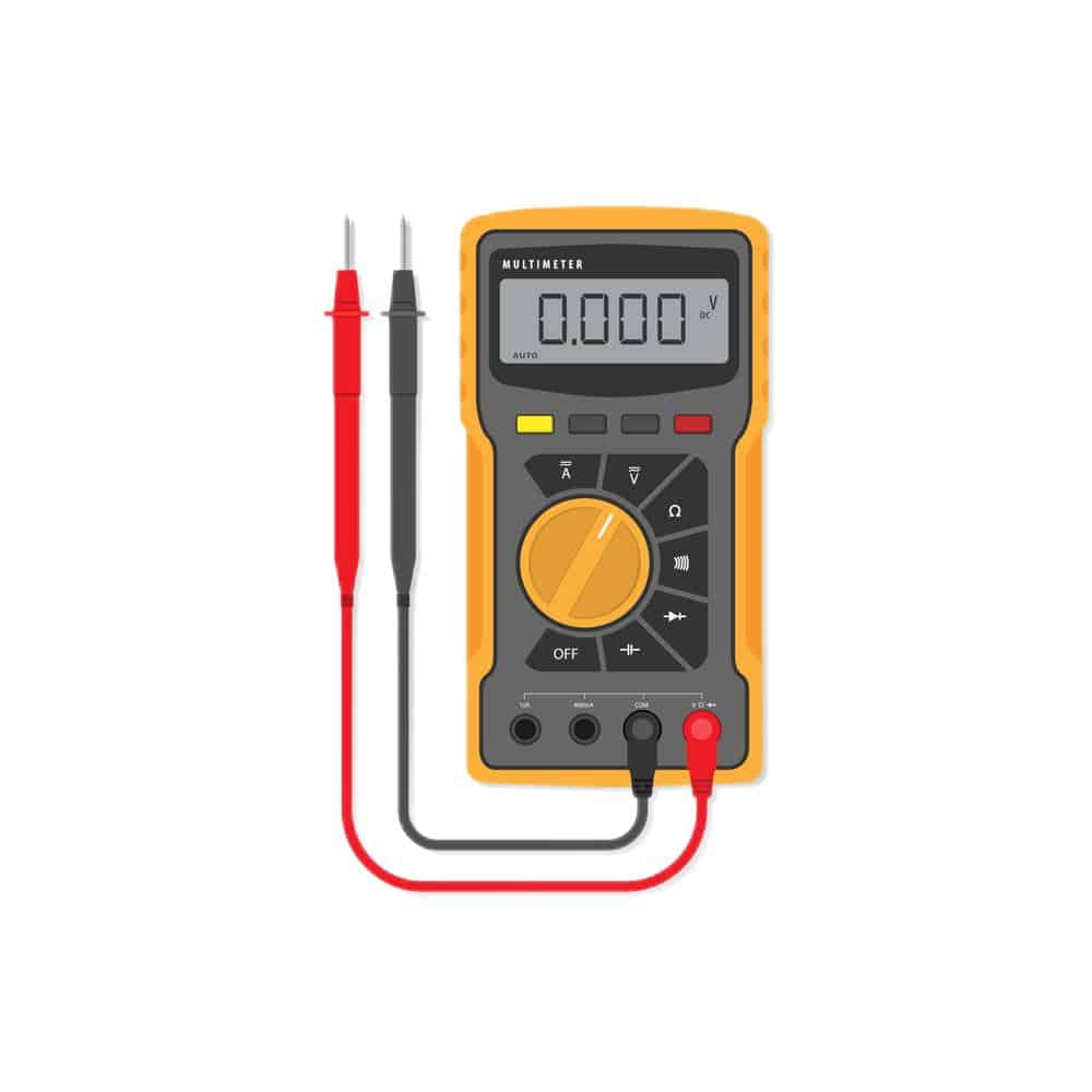
Another method to identify the polarity of a polarized capacitor is by using a multimeter, a handy tool for measuring electrical properties.
To identify the polarity of a polarized capacitor using a multimeter, set the multimeter to the resistance or ohm setting. Connect the red (positive) probe to one terminal of the capacitor and the black (negative) probe to the other terminal. If the resistance reading starts low and then increases, the terminal connected to the red probe is the positive terminal. If the resistance reading stays low or at zero, switch the probes.
Remember, this method should not be used for non-polarized capacitors as they do not have a specific positive or negative terminal.
Importance of Capacitor Polarity in PCB Design
Understanding capacitor polarity is not just a theoretical concept, but it has practical implications, especially in Printed Circuit Board (PCB) design. Here’s why capacitor polarity is crucial in PCB design:
- Ensuring Correct Functioning of the Circuit
The correct functioning of a circuit largely depends on the proper installation of its components, including capacitors. Polarized capacitors, such as electrolytic capacitors, must be installed in the correct orientation to function properly. If a polarized capacitor is installed in reverse, it can lead to the breakdown of the insulating oxide layer, potentially causing the capacitor to fail or even explode. This can lead to circuit malfunction or even damage to the PCB.
- Preventing Damage to the Capacitor and Circuit
Incorrect installation of a polarized capacitor can not only damage the capacitor itself but also other components in the circuit. When a polarized capacitor is connected in reverse, it can cause a short circuit, leading to excessive current flow. This can generate heat and potentially damage other components in the circuit.
- Enhancing the Efficiency and Lifespan of the Circuit
Correctly installed capacitors can enhance the efficiency and lifespan of the circuit. Capacitors play a crucial role in filtering noise, stabilizing voltage, and storing energy in a circuit. When capacitors are installed in the correct orientation, they can perform these functions more effectively, leading to improved circuit performance and longevity.
Conclusion
Understanding capacitor polarity is not just a theoretical concept but a practical one, especially when it comes to PCB design. Whether you’re a hobbyist or a professional, correctly identifying and installing capacitors in your circuits is crucial. It ensures the correct functioning of the circuit, prevents damage to the capacitor and other components, and enhances the efficiency and lifespan of the circuit.
For any inquiries, feel free to reach out to us at [email protected]. We’re here to help you navigate your PCB journey. Keep exploring, keep learning, and keep innovating.