Introduction
Have you ever been asked for a Gerber file when requesting a PCB quote and wondered what it is? Or perhaps you’ve only had a PCB file or a physical board and weren’t sure if that’s enough?
PCB production files, such as Gerber and PCB files, are the essential blueprints for PCB & PCBA manufacturing. They contain all the necessary details for creating your PCB exactly as designed. If you only have a PCB file or a physical board, don’t worry – Rowsum can convert PCB files to Gerber or use reverse engineering to create the necessary production files from a physical board. Now, let’s delve deeper into what these production files are and why they’re so important.
What are PCB Production Files?
In the world of PCB & PCBA manufacturing, PCB production files are akin to the DNA of your project. They contain all the necessary details that guide the manufacturing process, ensuring your PCB is created exactly as you’ve designed it.
There are several types of PCB production files, but the most common ones are Gerber files and PCB files.
Gerber files are the industry standard and are the preferred format for us here at Rowsum. These files are like a collection of blueprints, each representing a specific layer of the PCB. For instance, one Gerber file might outline the copper layer, indicating where the copper should be placed on the board, while another might detail the solder mask, showing where the protective solder mask layer should be applied. Each file is essentially a 2D binary image that defines the areas of a PCB layer, and they are used together to create the actual physical layers of a PCB.
PCB files, on the other hand, are specific to the software used to design the PCB. They contain more information than Gerber files, including the schematic and layout information. This can be incredibly helpful for troubleshooting and making modifications to the design.
Now, let’s move on to the next section to understand why we need these production files.
Why Do We Need Your Production Files?
For Quotation
When you approach us with a PCB project, the first thing we need to do is provide you with a quote. To do this accurately, we need your production files, specifically the Gerber files.
Why?
Gerber files contain detailed information about your PCB design, including:
- Board Outline: This shows the shape and size of the PCB, which impacts the amount of material needed and the manufacturing time.
- Layers: The number of copper layers, solder mask layers, silkscreen layers, etc., each represented by a separate Gerber file. More layers mean more complexity and higher costs.
- Drill Files: These show where holes need to be drilled on the PCB. The number and size of the holes can affect the manufacturing time and cost.
- Component Placement: This can be found in the silkscreen layer, showing where components should be placed. This is crucial for assembly and affects the complexity of the assembly process.
By analyzing these details, we can accurately estimate the materials, time, and processes needed to manufacture your PCB, allowing us to provide you with a precise and competitive quote.
For Manufacturing
Once we move past the quotation stage and into the actual manufacturing process, the Gerber files become even more critical.
Why?
The Gerber files serve as the blueprint for your PCB. They guide our machines on where to lay the copper tracks, where to drill the holes, and where to place the components.
Here’s a more detailed look at how Gerber files aid in the manufacturing process:
- Copper Traces: Gerber files provide the exact layout of the copper traces, which are crucial for electrical connections between the components. The width, thickness, and routing of these traces are all specified in the Gerber files.
- Drilling: The drill files included in the Gerber file set instruct our machines where to drill the holes for through-hole components and vias. The size and location of these holes are critical for component placement and internal connections between different layers of the PCB.
- Solder Mask and Silkscreen: The Gerber files also contain the layout for the solder mask, which prevents solder bridges, and the silkscreen, which labels the component positions. These are crucial for the assembly process and for future repairs or modifications.
- Quality Assurance: By comparing the manufactured PCB with the original Gerber files, we can ensure that the PCB has been produced accurately. This allows us to maintain high quality standards and catch any potential manufacturing errors.
- Component Sourcing: Gerber files can also be helpful during the component sourcing process. Sometimes, the BOM might not provide detailed descriptions of certain components. In such cases, we can refer to the Gerber files to determine the package type and other specifications of the components.
At Rowsum, we see these files as more than just technical documents. They are the bridge between your vision and the tangible product we create. They allow us to step into your shoes, understand your design in detail, and ensure that the final product meets your exact specifications.
Preferred File Format: Gerber – A Timeless Standard in PCB Manufacturing
The Gerber file format is the lingua franca of the PCB manufacturing world. But what makes it so universally accepted and preferred? In this section, we’ll explore the history, evolution, and the reasons behind Gerber’s prominence in the PCB industry.
Gerber: A Format That Grew with the Industry
The Gerber format has been a constant companion to the PCB manufacturing industry, evolving and adapting to its needs. It started as Standard Gerber or RS-274-D, a basic format that was adequate for the time but had its limitations.
As PCB designs grew more complex and demanded more from the file format, Extended Gerber or RS-274X came into existence. This format was a significant improvement, offering more features and capabilities to handle intricate designs.
In 2014, UCAMCO, the custodian of the Gerber file format, declared Standard Gerber “technically obsolete,” giving Extended Gerber the spotlight. The reason was straightforward: Standard Gerber’s lack of standardized aperture definitions could lead to misinterpretations and, consequently, manufacturing errors.
Today, we have Gerber X2, the latest iteration of Gerber, packed with features to support modern PCB manufacturing processes.
The Strengths of Gerber
The evolution of Gerber is a testament to its robustness, adaptability, and universal acceptance. Here’s why it remains the preferred file format for PCB manufacturing:
- Universality: Gerber is a format that transcends software boundaries. Almost all PCB design software can export designs in Gerber format, and all PCB manufacturers can interpret it. This universality ensures seamless communication between designers and manufacturers.
- Reliability: Gerber files are dependable. They encapsulate all the necessary information for manufacturing a PCB in a format that minimizes ambiguity, reducing the likelihood of manufacturing errors.
- Flexibility: Gerber files can represent all aspects of a PCB, from copper layers to solder masks, silkscreen, and drill holes. This flexibility makes them suitable for all types of PCBs, from simple single-layer boards to intricate multi-layer designs.
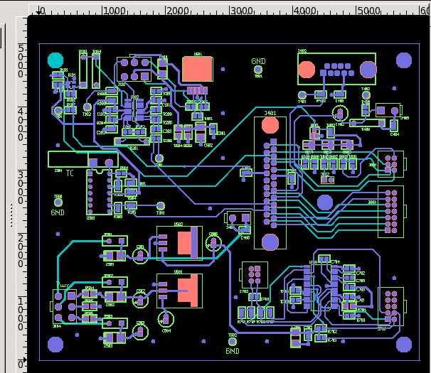
Decoding a Gerber File
A typical Gerber file set for a PCB design contains several files, each representing a different layer or aspect of the PCB. Here’s a snapshot of what each file typically represents:
- Copper Layers: These files depict the copper layers of the PCB. Each copper layer has its own file.
- Solder Mask: These files indicate where the solder mask should be applied. There’s a separate file for the top and bottom solder mask.
- Silkscreen: These files contain the silkscreen layers, which include the component labels and other markings on the PCB. Like the solder mask, there’s a separate file for the top and bottom silkscreen.
- Drill Files: These files indicate where holes need to be drilled on the PCB. They are often in a separate format called “Excellon”.
- Board Outline: This file outlines the shape and dimensions of the PCB.
| Gerber Files | Extension |
|---|---|
| Top (copper) Layer | .GTL |
| Bottom (copper) Layer | .GBL |
| Top Overlay | .GTO |
| Bottom Overlay | .GBO |
| Top Paste Mask | .GTP |
| Bottom Paste Mask | .GBP |
| Top Solder Mask | .GTS |
| Bottom Solder Mask | .GBS |
| Keep-Out Layer | .GKO |
| Drill Drawing | .GD1 |
| Drill Guide | .GG1 |
| Internal Plane Layer1,2,…,16 | .GP1, .GP2, … , .GP16 |
In the next section, we’ll delve into how you can generate these Gerber files from your PCB design software.
How to Generate Gerber Files from Your PCB Design Software
Creating Gerber files from your PCB design software is a crucial step in the PCB manufacturing process. This process can vary depending on the software you’re using. In this section, we’ll guide you through the process of generating Gerber files from two of the most popular PCB design software: Eagle and Altium Designer. We’ll also cover how to convert Gerber files to other formats using GerbView, a widely-used Gerber file viewer and converter.
Generating Gerber Files from Eagle
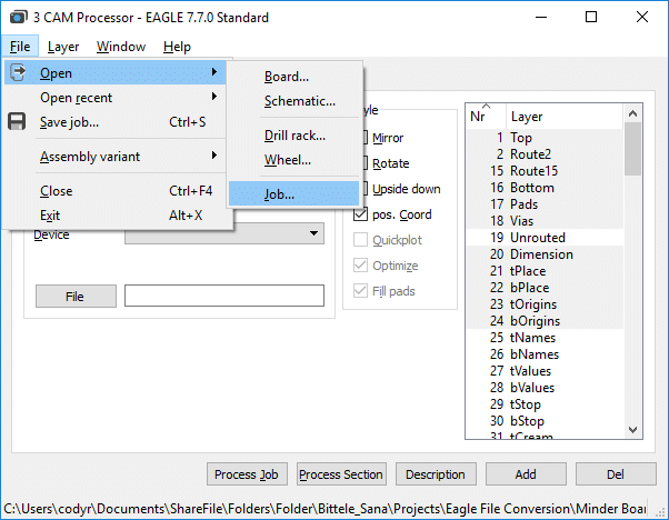
Eagle is a widely-used PCB design software. If you’re using Eagle for your PCB design, you’ll need to generate Gerber files from your design to send to your PCB manufacturer. Here’s a step-by-step guide on how to do it:
- Open Your Board Design: Launch Eagle and open your completed board design.
- Open CAM Processor: Go to the “File” menu, select “CAM Processor”. This will open a new window.
- Load the Gerber CAM Job File: In the CAM Processor window, go to “File”, then “Open”, and select “Job…”. From the options, choose “gerb274x.cam” for the Gerber files.
- Run the CAM Job: Click on “Process Job”. Eagle will generate the Gerber files and save them in the same directory as your board design file.
- Generate the Drill Files: Go back to the “Open Job” option and this time select “excellon.cam”. Click on “Process Job” again to generate the drill files.
- Review the Generated Files: You should now have a set of Gerber and drill files in your directory. Review these files using a Gerber viewer to ensure everything looks correct.
- Zip the Files: Finally, compress all the Gerber and drill files into a single .zip file. This is the file you’ll send to your PCB manufacturer.
This is a brief overview of the process. For a more detailed guide, you can refer to this comprehensive tutorial on Generating Gerber Files from Eagle.
Generating Gerber Files from Altium Designer
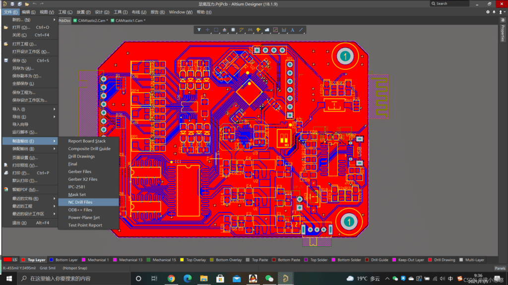
Altium Designer is another popular PCB design software used by many engineers and designers. If you’re using Altium Designer, you’ll need to generate Gerber files from your design to send to your PCB manufacturer. Here’s a step-by-step guide on how to do it:
- Open Your PCB Design: Launch Altium Designer and open your completed PCB design.
- Access the Gerber Files Setup: Navigate to the top menu, click on ‘File’, then ‘Fabrication Outputs’, and finally ‘Gerber Files’. This will open a new window where you can configure your Gerber file settings.
- Set the General Parameters: In the ‘General’ tab of the new window, set the ‘Units’ to ‘Millimeters’ and select the appropriate ‘Format’ for the output control information.
- Select the Layers: Switch to the ‘Layers’ tab and select all the layers for which you want to generate Gerber files. You can do this by checking the ‘Plot’ box for each layer. Alternatively, you can select ‘Used On’ from the ‘Plot Layer’ dropdown menu, which will automatically select all the layers used in your design.
- Configure the Drill Drawing: In the ‘Drill Drawing’ tab, you can optionally assign the formation of layers with the drill drawings and the designations of the drill guide. This step is optional and can be left to the default settings if not necessary.
- Set the Apertures: In the ‘Apertures’ tab, you can optionally activate the ‘Embedded Apertures (RS274X)’ option. If you select this option, the output file will be generated in the RS274X format. Please note that you should only select this option if your PCB manufacturer accepts RS274X format.
- Set the Advanced Options: In the ‘Advanced’ tab, select the ‘Separate file per layer’ option in the ‘Batch Mode’ field. This will generate a separate data file for each layer.
- Generate the Gerber Files: After you have made all the necessary settings in the Gerber setup popup, click the ‘OK’ button. This will generate the Gerber files, which will be saved at the location you selected.
- Examine the Gerber Files: Finally, examine the generated Gerber files for common issues, such as vectorized pads and obsolete file formats. You can address and rectify these problems using CAD and DFM tools.
This is a brief overview of the process. For a more detailed guide, you can refer to this comprehensive tutorial on Generating Gerber Files from Altium Designer.
4.3 Converting Gerber Files to Other Formats
There may be instances where you need to convert your Gerber files to other formats. This could be due to a variety of reasons such as needing to view the files in a different software, sharing the design with someone who doesn’t have a Gerber viewer, or needing to edit the design in a different software.
Here’s a brief guide on how you can convert Gerber files to other formats using GerbView:
- Download and Install GerbView: Visit the GerbView website and download the software. Install it on your computer.
- Open GerbView: Launch the software on your computer.
- Load Your Gerber File: Go to the “File” menu, select “Open”, and navigate to your Gerber file. Select the file and click “Open”.
- Select the Output Format: Go to the “File” menu, select “Save As”. A dialog box will appear. Here, you can select the format you want to convert your Gerber file to.
- Save the File: Choose the location where you want to save the converted file, give it a name, and click “Save”.
This is a simplified overview of the process. For a more detailed guide, you can refer to the comprehensive tutorial on the GerbView website.
What if You Don’t Have Gerber Files?
In an ideal world, everyone who needs PCB & PCBA manufacturing services would have their Gerber files ready. However, we understand that this is not always the case. You might be in a situation where you don’t have Gerber files for your PCB design. Don’t worry; there are still options available for you.
Providing Other PCB Design Files
If you don’t have Gerber files, but you have your PCB design in another format, that’s still workable. Many PCB design software can export the design into different file formats. For example, you might have files in the format of Altium, KiCad, or Eagle.
At Rowsum, we can accept these files and convert them into Gerber files on our end. This conversion process is usually straightforward and doesn’t cause any significant delays in the quotation or manufacturing process.
Using Reverse Engineering Services
In some cases, you might only have a physical PCB but no design files. This situation is more challenging but not impossible to handle. At Rowsum, we offer reverse engineering services.
Our team of experienced engineers can analyze your physical PCB and recreate the PCB design files, including Gerber files. This process is more time-consuming and might incur additional costs, but it allows you to proceed with your PCB & PCBA manufacturing project even if you don’t have any design files. To learn more about how reverse engineering can save your business from costly downtime, you can refer to our previous article here.
In conclusion, while having Gerber files is preferred, it’s not the end of the world if you don’t have them. There are alternatives available, and at Rowsum, we’re committed to helping you navigate through these situations.
Conclusion
In essence, PCB production files, particularly Gerber files, are the blueprint for your PCB design. They contain all the necessary information for a PCB manufacturer to accurately produce your design. Whether you’re an engineer creating complex designs or a hobbyist working on a personal project, understanding these files and how to generate them is crucial.
At Rowsum, we’re more than just a PCB manufacturer. We’re your partner in bringing your electronic designs to life. We offer a range of services, including PCB Manufacturing, PCB Assembly, and Components Sourcing to help you at every stage of your project.
If you have any questions or need further assistance, don’t hesitate to reach out to us at [email protected]. We’re always here to help.